AI-assisted Multi-Sensor Fusion for Enhanced Autonomous Vehicle Navigation
Jorge Morán García, Philipp Bohlig, Robert Bensch, Luka Sachsse, Sai Parimi, Frieder Schmid, Julian Dey, Olena Horokh, Jan Fischer, ANavS GmbH
BIOGRAPHY (IES)
Jorge Morán García is a Project Manager at ANavS, leading multiple European initiatives on high-accuracy and integrity localization solutions that combine GNSS (RTK and PPP-AR) with sensor fusion approaches using cameras, LiDARs, and other sensing technologies. He is also coordinating the DREAM project (DRiving aids by E-GNSS AI and Machine learning), which forms the basis for the research and results presented in this paper.
Philipp Bohlig is the Head of the GNSS and Sensor Fusion group within ANavS. His fields of expertise and research cover tightly-coupled sensor fusion, Precise Point Positioning (PPP), Integer Ambiguity Resolution (IAR) and GNSS integrity. As Head of the GNSS and Sensor Fusion group within ANavS, he coordinates and supervises technical activities in the development of multi-sensor positioning algorithms.
Robert Bensch leads the computer vision team at ANavS. The team focus is on precise and robust positioning in GNSS denied or degraded areas using camera and LiDAR sensors, as well as on environment detection and mapping. He received his PhD degree in applied computer science from the Albert-Ludwigs-Universität Freiburg, Germany, with focus on biomedical image analysis and motion pattern analysis. Dr. Bensch joined ANavS in 2017 and has been building up the computer vision team for several years.
Luka Sachsse is a software engineer in the ANavS Computer Vision Team. His work focuses on the integration of Visual SLAM/Odometry in the localization software of ANavS. He has contributed to the development of advanced vehicle and robot localization algorithms within multiple research projects.
Sai Parimi is a computer vision expert at ANavS GmbH. He works on environment perception using LiDARs with a major focus on LiDAR SLAM and 3D object detection. He received his M.Sc. degree in Electrical and Computer Science Engineering from Darmstadt University of Applied Sciences, Germany. He graduated in 2021 with a master’s thesis from Fraunhofer-Institut für Produktionstechnik und Automatisierung working on real-time pointcloud segmentation for industrial object detection to improve bin picking robot’s sorting algorithm. He has been working at ANavS GmbH since 2022.
Frieder Schmid is a Software Engineer at ANavS GmbH in Munich, Germany. The focus of his work at ANavS is the navigation of moving objects. He completed his master’s degree in Geodesy and Geoinformatics at the University of Stuttgart in 2024, with his degree in the field of navigation, parameter estimation, and sensor fusion.
Julian Dey is working in the GNSS and Sensor Fusion group within ANavS. His fields of expertise and research cover tightly-coupled sensor fusion, Precise Point Positioning (PPP), and Integer Ambiguity Resolution (IAR).
Olena Horokh is an engineer at ANavS Computer Vision Team. Focuses on Visual SLAM and Visual Localization (inc. 3D Localization maps generation) with integrated Semantic scene information (Segmentation, Object Detection). She completed her master’s degree in 2023 in Computational Modeling and Simulation (Visual Computing track) at the Technical University of Dresden, Germany. She has been working at ANavS GmbH since 2022.
Jan Fischer completed his master’s degree in Mechatronics and Information Technology at the Karlsruhe Institute of Technology. Since 2022 he has been working as a data fusion and computer vision engineer at ANavS GmbH. His main focus at ANavS is the Multi-Sensor RTK and visual SLAM system.
ABSTRACT
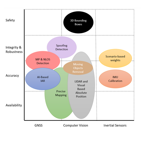
Autonomous vehicles demand navigation systems that deliver high levels of accuracy, availability, and integrity under all operating conditions. Urban environments pose particular challenges, with GNSS performance degraded by multipath, non-line-of-sight (NLOS) conditions, and intentional or unintentional interference. To meet these requirements, multi-sensor fusion has become the de-facto approach, combining GNSS with inertial and perception sensors.
A core contribution of our work is the integration of multiple AI approaches to improve the robustness and accuracy of the system in challenging urban scenarios. Although many sensor fusion techniques have been proposed to address these issues, few integrate advanced artificial intelligence (AI) methods to enhance the performance and reliability of each subsystem.
The system follows a semi-tightly coupled architecture. At the core, a tightly coupled multi-antenna GNSS/INS subsystem operates alongside two parallel modules based on LiDAR-inertial and visual-inertial SLAM. These subsystems are integrated in a federated Kalman filter, which loosely combines their outputs to improve reliability and robustness.
AI modules are deployed at several levels of this framework to address limitations of conventional methods. For GNSS, three independent neural networks are employed to detect and mitigate multipath and NLOS signals, identify and counteract jamming and spoofing, and improve ambiguity resolution. In addition to GNSS enhancement, the paper addresses challenges related to the inertial navigation component. An AI-based adaptive calibration approach is proposed, that refines IMU calibration and dynamically adjusts the confidence levels of pseudo-measurements used in state estimation. The proposed system combines both
elements by using a Multitask Deep Neural Network (MTDNN) architecture capable of using additional sensor data — such as odometry, camera and lidar information — alongside the raw IMU signals to the network. For LiDAR and Visual based localization, an AI-based method is used to detect and remove dynamic features, ensuring that pose estimation relies on static elements of the environment and improving accuracy in dense traffic scenarios.
A distinctive aspect of this work is the focus on real-time implementation under resource constraints. Neural network architectures and SLAM modules have been optimized to run on embedded hardware, ensuring feasibility for deployment in automotive platforms.
INTRODUCTION
Autonomous driving represents one of the most demanding applications for navigation and perception systems. Key performance indicators such as accuracy, availability, and integrity must be guaranteed at levels that leave minimal margin for error. Even short-term degradations in performance can have serious safety implications, especially in complex traffic scenarios.
In urban environments, these challenges are amplified. GNSS signals suffer from multipath reflections, frequent blockages due to high-rise buildings, and non-line-of-sight (NLOS) conditions. In addition, interference and spoofing remain plausible threats to satellite-based positioning. For this reason, autonomous vehicle navigation cannot rely on GNSS alone but must combine information from multiple complementary sensing modalities.
DREAM (DRiving aids by E-GNSS AI and Machine learning) is a project funded under EUSPA’s Fundamental Elements program that addresses these challenges by developing innovative AI/ML methods for positioning and perception. Its final goal is to provide highly accurate and reliable information that can support advanced driver assistance systems (ADAS), such as Red Light Violation Warning, Curve Speed Warning, Collision Avoidance, and Wrong-Way Driving. DREAM combines GNSS, inertial, and LiDAR/visual sensors in a well-balanced way, exploiting the advantages of each while mitigating their individual limitations. In addition to navigation, the project also develops 3D bounding boxes for object detection and geo-referenced maps to improve localization and situational awareness. ANavS, as a leading company in the development of high-precision navigation systems for a wide market segment including the automotive sector, is conducting DREAM by combining classical algorithms with state-of-the-art AI and ML techniques.
The work presented in this paper builds on the DREAM framework, introducing a navigation solution that integrates GNSS, IMU, LiDAR, and visual data in a semi-tightly coupled architecture. The system incorporates AI-based techniques at multiple levels: improving GNSS reliability under degraded conditions, refining IMU calibration and measurement adaptation, and enhancing SLAM accuracy through the detection and removal of dynamic features. The entire solution is implemented on embedded hardware, ensuring real-time operation under the resource constraints imposed by automotive platforms.
The remainder of this paper is organized as follows. Section 2 describes the overall system architecture. Section 3 presents the AI-based techniques applied to the GNSS, IMU, and SLAM subsystems. Section 4 discusses the test setup and summarizes results from a data campaign conducted in challenging real-world scenarios. Finally, Section 5 concludes the paper and outlines the next steps.
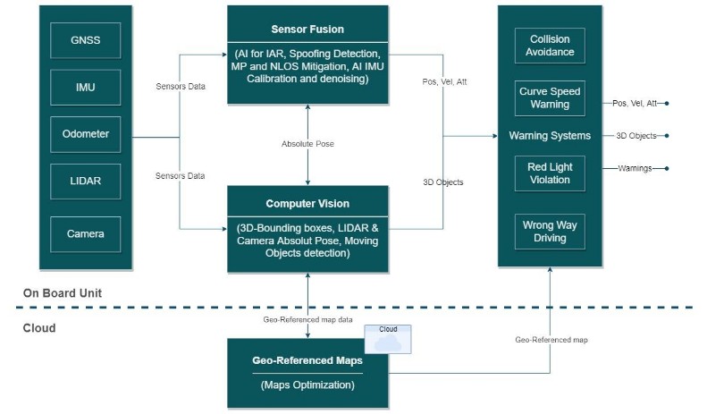
SYSTEM ARCHITECTURE
The system architecture is organized in a semi-tightly coupled framework. At the front end, a tightly coupled multi-antenna GNSS/INS subsystem processes raw GNSS signals together with inertial measurements. In parallel, two additional tightly coupled subsystems—one based on LiDAR inertial SLAM and the other on visual inertial SLAM—provide independent estimates of the vehicle’s position and orientation. Both sensors are complementary. LIDAR offers several advantages, such as accurate and immediate depth measurements, larger field-of-view (FOV), when using a rotating LIDAR with 360° horizontal FOV, it works at night and is robust against lighting changes or low-light conditions, since it is an active sensor emitting light.
Cameras on the other hand offer other advantages, they are usually cheaper, offer higher framerates and provide colour and texture information, which is relevant for object detection.
The proposed LIDAR and visual absolute positioning approach is based on an optimized and georeferenced map provided by an offline mapping module and provided to the real-time LIDAR and visual SLAM algorithms running on the embedded vehicle’s platform. During operation on the vehicle’s platform the SLAM approach is first initialized to the correct pose in the georeferenced map and then used for localization in the 3D point cloud map.
The outputs of the three localization subsystems are then combined using a federated Kalman filter that operates in a loosely coupled manner. This multi-layered approach is designed to compensate for the individual limitations of each sensor modality, ensuring continuous and reliable positioning even when GNSS signals are compromised.
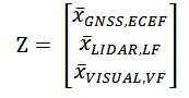
In the loosely coupled implementation, also referred as Central Filter (CF), the states estimated by the filter are:
Being 𝑟̅ and 𝑣̅ (∈ 𝑅3) the position and velocity vectors. 𝑞 ∈ 𝑅4, is the quaternion representing the attitude without potential singularities. The biases of the accelerometer and the gyroscope in the body fixed frame are denoted with ![]()
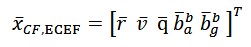
The prediction step of the Kalman Filter uses the acceleration and angular rate provided by the IMU sensor. The measurement vector for the update step of the central EKF filter can be expressed as:
Being:
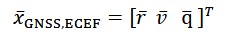
The pose from the GNSS PPP filter is given in the ECEF frame while the pose/twist from the camera/Lidar SLAM might be referring to a local frame or in the ECEF frame (when supported by an offline generated geo-referenced map). Therefore, the multi-pose filter has to estimate the transformation between different frames along the other parameters. The transformation of the ECEF position 𝑟𝐸𝐶𝐸𝐹 into the Lidar position 𝑟𝐿𝑖𝑑𝑎𝑟 is given by
Where![]()
is the rotation and translation from the ECEF frame into the Lidar frame. Both quantities are estimated
in the multi-pose filter. The same is done for the visual-based estimated position.
Dealing with relative pose measurements, such as those obtained from camera and lidar sensors, poses challenge in filtering scenarios. Stochastic cloning was presented by Roumeliotis and Burdick [1] to include relative measurements directly and formally correct them. It introduces a state augmentation by cloning the respective state estimates connected by the relative measurement. This enables the filtering algorithm to dynamically adapt to the evolving spatial context. Stochastic cloning excels in maintaining the integrity of the filtering process, ensuring that uncertainties associated with relative measurements are appropriately considered. Thus, it provides a robust and effective framework for state estimation in scenarios involving relative and absolute pose measurements
AI-BASED METHODS FOR GNSS, IMU, AND SLAM ENHANCEMENT
In the following subsections, we detail how AI has been applied across the three main components of the proposed system:
- GNSS, where three independent networks are used to 1) identify and mitigate the effects of multipath and NLOS conditions 2) integer ambiguity resolution candidate selection and 3) jamming and spoofing monitoring, providing an additional layer of security by ensuring that only reliable GNSS measurements are used in the state estimation process.
- IMU, where AI enhances calibration and adapts noise models in real time.
- LiDAR and visual based localization, where AI helps to improve pose estimation by identifying and filtering out
dynamic objects.
GNSS
The quality of GNSS observations is crucial for reliable state estimation, and errors caused by multipath and NLOS signals remain major challenges. Traditional outlier checks often fail to adequately detect these signals or require high computational effort, which limits their applicability in real-time systems. To address this limitation, we set-up an AI-based approach that identifies faulty signals directly from raw GNSS measurements. Instead of relying solely on statistical consistency checks, the neural network learns intrinsic patterns and characteristics associated with MP and NLOS conditions.
The developed model identifies NLOS satellites by performing a binary classification for each observation. Its input features include normalized carrier-to-noise ratio (C/N0), signal lock time, least-squares positioning residuals, and pseudorange consistency [6]. To capture inter-satellite dependencies within a GNSS epoch, the network employs a long short-term memory (LSTM) layer that processes all measurements jointly, followed by a fully connected layer with ReLU activation for the final classification. The resulting NLOS likelihood enables the Precise Point Positioning (PPP) engine to discard unreliable signals before they enter the estimation process.
Integer Ambiguity Resolution (IAR) plays a crucial role in achieving fast convergence and centimeter-level accuracy in PPP. A widely used technique for IAR is the LAMBDA [5] method, which generates multiple integer-valued ambiguity candidates derived from float estimates and their covariance matrix. The critical problem is then the selection of the correct candidate among several plausible solutions.
AI offers a promising approach to address this challenge by supporting candidate selection. Specifically, AI can classify each candidate as valid or invalid based on statistical and measurement-specific features. General parameters, such as the ambiguity dilution of precision (ADOP) and position standard deviations, are processed using fully connected neural layers. In parallel, ambiguity-specific parameters—such as float ambiguity values and carrier-to-noise density ratio (CN0) of the corresponding measurements—are well suited for sequence modeling through LSTM networks.
This hybrid approach allows for the integration of both global and ambiguity-level characteristics, incorporating temporal and epoch-wise dependencies. The AI model produces a likelihood score for each ambiguity candidate, enabling the PPP engine to reliably select the correct solution. By leveraging a broader set of input parameters than the classical FFR test, it can exploit additional measurement features, enabling a more informed classification.
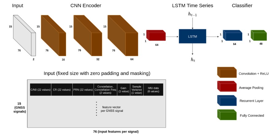
The system also incorporates an AI-based model for interference detection, capable of identifying GNSS signals affected by jamming, meaconing, and spoofing attacks. The model proposed by Bohlig et al. [2] uses a hybrid architecture combining a convolutional neural network (CNN) encoder with an LSTM network. The CNN extracts relevant feature representations from GNSS and IMU measurements, including gain amplifier values, carrier-to-noise ratios, cross-band carrier-phase divergence, and sample variance. It further captures inter-signal correlations and local measurement patterns. The output of the final CNN layer is aggregated using average pooling to produce an embedding vector summarizing the signal-level information to the LSTM, which captures the temporal dependencies [2]. A multi-label classification layer outputs the interference classification specifying which GNSS signals across multiple constellations are impacted
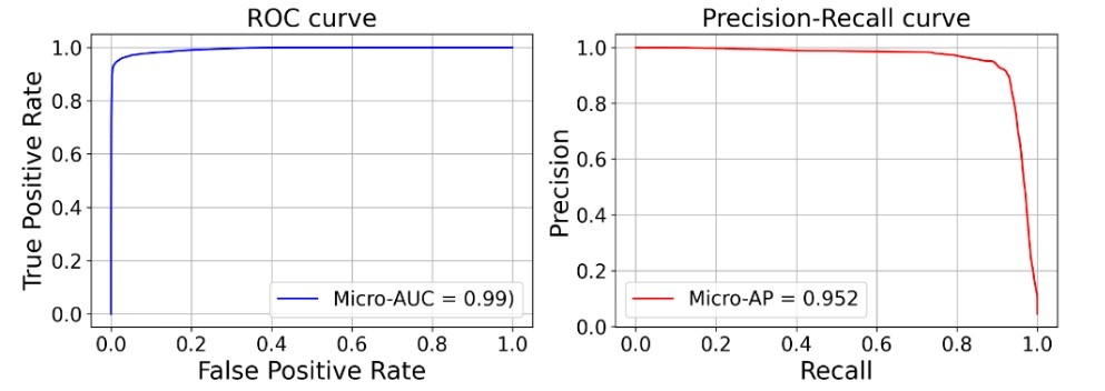
The network has been trained and validated on real data collected during the JammerTest 2024 campaign in Andøya, Norway. This controlled campaign provided a predefined transmission plan detailing the interference type, time, affected carriers, and coverage area. The transmission plan enables the derivation of precise ground-truth labels for both the type of interference and the corresponding affected signals, ensuring a reliable dataset for training and evaluation.
Figure 4 shows that the classification works well to identify the interference type per signal as visualized by the metrics combining all labels, i.e., the high Micro-Area under curve (AUC) of 0.99 and the good precision and recall, which is above 0.9. By doing so, the overall system excludes signals with identified interference and keeps using other GNSS signals to maintain accuracy and availability.
IMU
In addition to GNSS enhancement, the paper addresses challenges related to the inertial navigation component. Accurate inertial navigation is essential for reliable state estimation in autonomous vehicles. Traditional IMU calibration methods often fail tocapture time-varying characteristics and nonlinear, non-Gaussian noise. On the other hand, autonomous vehicles often rely onpseudo-measurements, known as Non-Holonomic Constraints (NHCs), to integrate prior knowledge of vehicle dynamics intothe state estimation process. However, during manoeuvres such as turns, or when experiencing sideslip and minor vertical
movements, these assumptions may no longer hold. Relying on a fixed confidence level for NHCs in such dynamic conditionscan lead to inaccuracies in the state estimation. Therefore, it is crucial to adapt the confidence in these pseudo-measurementsdynamically by continuously adjusting the associated variance-covariance matrix.
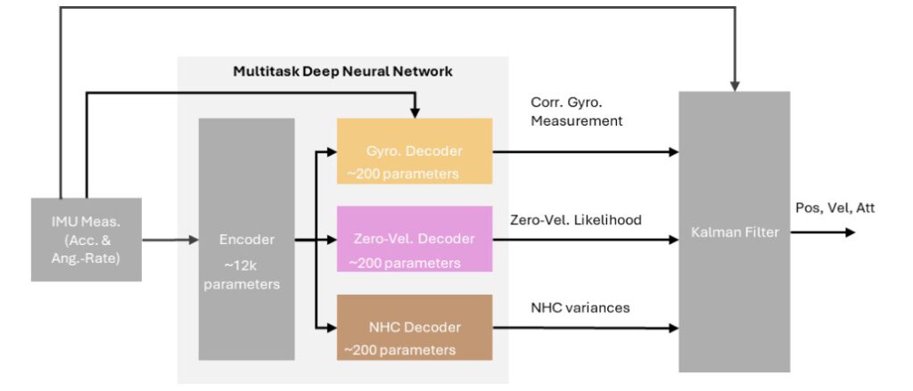
To address these limitations, we have developed an AI-based adaptive method that refines IMU calibration and dynamicallyadjusts the confidence levels of pseudo-measurements used in state estimation. The system also integrates a LSTM network todetect both zero-velocity and zero-angular-rate constraints, which are then incorporated as pseudo-measurements in a Kalmanfilter. The proposed system combines the three elements by using a Multitask Deep Neural Network (MTDNN) architecture andmakes use of additional sensor data — such as odometry, camera and lidar information — alongside the raw IMU signals to the network. This way the network achieves better generalization and less overfitting while with the reduced computational overheadthrough parameter sharing, enables deployment on resource-constrained systems.
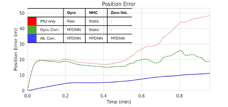
For evaluation of the proposed framework, Figure 6 contains the position error results (using only IMU data to estimate the position) presented by Schmid and Fischer [3] for a single sequence from the 4Seasons dataset. Compared to the raw IMU setup with static NHC (red) and the gyroscope-corrected variant still relying on static NHC (green), the full multitask system (blue) achieves the best performance by integrating all corrections. Furthermore, the model’s runtime performance was evaluated on a Raspberry Pi 5 and confirmed that it achieves inference rates significantly exceeding the 125 Hz IMU sampling frequency, demonstrating its suitability for real-time embedded deployment.
Visual and LiDAR based localization
The integration of AI also extends to the LiDAR SLAM and visual based localization modules. Standard SLAM algorithms often operate under the assumption of a static environment, using differences between consecutive measurements to estimate the vehicle’s pose. However, urban scenes are frequently affected by moving objects such as vehicles and pedestrians. To address this, an AI-driven moving object detection and removal mechanism is incorporated into the SLAM process. This mechanism filters out dynamic elements from sensor data, allowing the SLAM algorithm to focus on static features that are critical for accurate pose estimation. This step is particularly beneficial in busy urban intersections or dense traffic scenarios, where dynamic objects could otherwise lead to significant estimation errors.
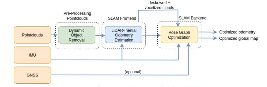
The LiDAR SLAM architecture follows a tightly coupled frontend–backend design with an initial point cloud preprocessing stage. The frontend is based on FAST-LIO2 [8], where LiDAR point clouds (also referred as scans) and IMU measurements from the Ouster OS1-128 sensor are tightly integrated to provide odometry estimates. These odometry estimates are then further refined in a factor graph-based backend, which incorporates an IMU prior factor for initialization and uses relative poses and loop closures as between-factors in the optimization process. The de-skewed point clouds are subsequently transformed using optimized poses and stitched together, resulting in a globally consistent map. In this paper, the focus is placed specifically on the dynamic object removal module integrated into the frontend stage. For a complete description of the full LiDAR SLAM system, the reader is referred to Parimi and Bensch [7].
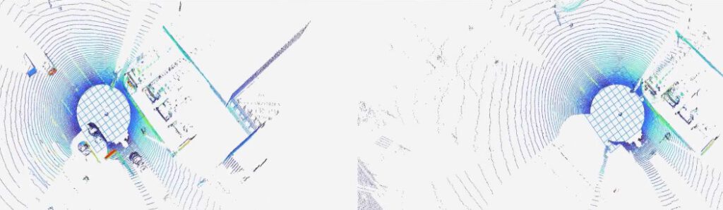
Removing dynamic objects from LiDAR point clouds is a critical step for robust localization and mapping. The algorithm processes raw LiDAR scans and outputs filtered point clouds with moving objects removed. Each scan contains above one hundred thousand points at 20 Hz, which poses a challenge for real-time operation.
To achieve this, the point clouds are semantically segmented to identify classes likely to be dynamic, such as cars, trucks, bicycles, pedestrians, and motorcycles. The cleaned point clouds are then aggregated in a sliding window covering several consecutive frames. To compensate for the ego vehicle motion, each point cloud is first transformed into a common reference frame. This step ensures that static objects remain spatially aligned across the window, while dynamic objects can be detected through their relative motion. The aggregated point cloud is partitioned into voxel grids, and the stability of points across frames is tracked: points that remain within the same voxel throughout the sliding window are classified as static, while points that shift between voxels are labelled dynamic and removed.
For Visual Inertial Odometry, Figure 9 illustrates the pipeline proposed by Sachße et al. [4] for dynamic object removal from camera-based localization. The process begins with instance segmentation performed on the left image of the stereo pair using a pre-trained Mask R-CNN model with a ResNet backbone implemented in the MMDetection framework. The goal of this step is to classify and separate different types of objects in the scene, distinguishing static elements such as buildings, trees, or traffic lights from potentially dynamic road users such as cars, bicycles, or pedestrians.
Since instance segmentation is computationally expensive, it cannot be executed at the full frame rate required by the odometry estimation system. To address this limitation, a mask propagation strategy is introduced. This mechanism propagates the segmentation masks from frames where instance segmentation has been performed to intermediate frames, thus reducing the processing load while maintaining temporal consistency.
Finally, the dynamic status of the detected object instances is evaluated. This is achieved by applying epipolar geometry constraints to the segmentation masks, enabling the system to detect and filter out features associated with moving objects. The resulting mask filtering out dynamic instances is applied to the visual odometry pipeline ensuring that only static features are used for pose estimation.
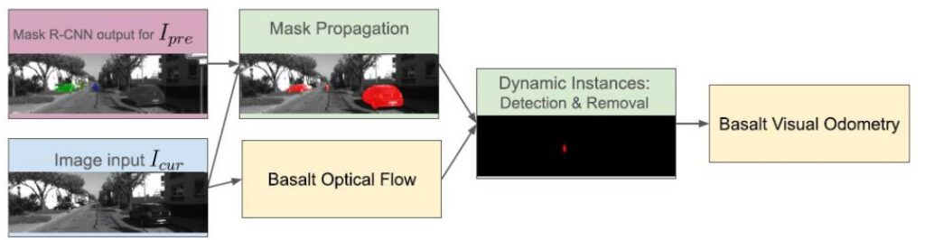
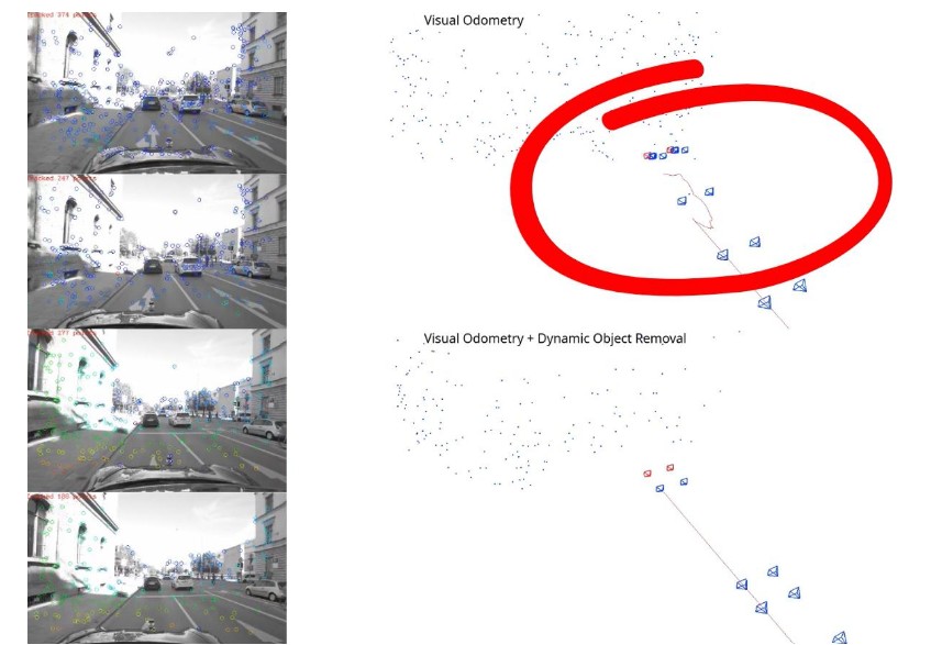
Figure 10 illustrates the impact of integrating the proposed AI-based dynamic object removal into the visual odometry pipeline. The figure is divided into two parts: the upper section shows results from the classical visual odometry approach, while the lower section shows the enhanced approach with dynamic object removal.
On the left side, images from the stereo camera are displayed with the tracked features used for localization. In the classical approach (top), features are extracted from both static and moving objects in the scene. In contrast, with dynamic object removal (bottom), features corresponding to surrounding dynamic vehicles are filtered out, leaving only static environmental features.
On the right side, the corresponding estimated trajectories are presented. In this frame, the ego vehicle is static while surrounding vehicles are in motion. Without dynamic feature removal (top), the algorithm incorrectly interprets the ego vehicle as moving,as features from moving cars bias the motion estimation. With the proposed method (bottom), moving objects are excluded, and the estimated trajectory correctly remains static. This demonstrates how AI-based dynamic object removal improves localization
accuracy in dense traffic scenarios where many features originate from non-static elements.
SYSTEM RESULTS
Scenario and car set-up
The system has been installed on one of our dedicated test vehicles, which serves as a platform for validating multi-sensor fusion and AI-based localization algorithms. The complete sensor configuration is illustrated in Figure 11.
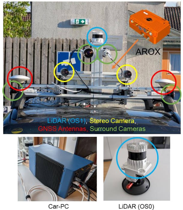
On the rooftop of the vehicle, the main localization sensors are mounted. An Ouster OS1-128 LiDAR (highlighted in blue) provides high-resolution 3D point clouds for SLAM and perception. Two Basler stereo cameras (yellow) are oriented forward to capture synchronized images. In addition, two GNSS antennas (red) are mounted to enable precise attitude determination in combination with the GNSS/INS subsystem.
Inside the vehicle, the on-board processing is split across two dedicated systems. A Car PC hosts the computer vision algorithms, while the ANavS AROX system (orange) executes the tightly coupled GNSS/IMU filter and the multi-sensor fusion algorithm. Both systems are interconnected using the ROS2 middleware, which provides a standardized communication layer for sharing sensor data and fusion outputs in real time.
Beyond these main localization components, the platform is further equipped with surround cameras (green) and an additional LiDAR sensor (OS0-128) located at the front of the vehicle. These additional sensors are used for object detection and environmental perception tasks. Since this paper focuses on localization aspects, they are not described in detail here.
The validation campaign was conducted in an urban environment in the city of Munich. The trajectory includes segments of wide streets with open visibility. These sections provide suitable conditions for assessing baseline system performance. In contrast, the trajectory also covers narrow streets surrounded by high buildings and dense vegetation, creating challenging multipath and non-line-of-sight conditions. These segments stress the robustness of the GNSS subsystem and the ability of the fusion framework to maintain positioning accuracy in degraded environments.
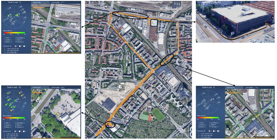
A particularly demanding part of the scenario is a full indoor section consisting of three loops inside an indoor parking facility. This environment completely denies GNSS signals and requires localization to rely exclusively on inertial and vision/LiDAR-based subsystems. Additionally, the trajectory includes bridge crossings, which cause temporary GNSS signal blockages. These conditions provide further opportunities to assess the capability of the system to bridge short-term outages and quickly recover once signals are reacquired.
Overall, the chosen scenario combines open-sky, obstructed urban, GNSS-denied, and intermittent conditions into a single trajectory, offering a comprehensive test environment for evaluating the proposed multi-sensor and AI-enhanced navigation framework.
To estimate the ground truth trajectory, a reference system, integrating GNSS and INS sensors, supplemented with a wheel odometer, will be used. The reference system’s use of RTK (Real-Time Kinematic) corrections significantly enhances its accuracy compared to the INS-aided PPP (Precise Point Positioning) solution utilized in DREAM. RTK solutions are known to be an order of magnitude more precise than PPP, thereby offering a superior benchmark for assessing our system’s performance. By leveraging all available satellite constellations, including GPS, GAL, and BDS, the reference system mitigates the risk of satellite geometry issues and improves the reliability of the ground truth data.
To further refine the ground truth trajectory, a Rauch-Tung-Striebel (RTS) smoother is applied. The RTS smoother effectively reduces errors by processing the data in both forward and backward directions, which is particularly beneficial in degraded conditions where signal quality may be compromised. This technique provides a more precise and reliable reference trajectory against which our system’s performance can be rigorously compared.
To ensure the accuracy of the ground truth system even in indoor conditions a FOG (Fiber Optic Gyroscope) IMU is employed. The FOG IMU offers superior performance in terms of precision and stability compared to the MEMS IMU used in the DREAM system. Technically, FOG IMUs provide higher accuracy and lower drift rates due to their reliance on the interference of light rather than mechanical parts, resulting in significantly enhanced inertial measurements.
AI-Assisted multi-sensor fusion results
The different localization subsystems—tightly coupled GNSS/IMU, LiDAR-based SLAM, and visual-inertial odometry—are combined through a loosely coupled federated filter, as introduced in Section 2. Each first-layer subsystem independently estimates the vehicle pose and provides its associated uncertainty. The central filter fuses these pose estimates by weighting them according to their reported covariance.
This design ensures that the fusion logic is driven by the reliability of the individual estimates. This means that in favourable GNSS visibility conditions, the central filter relies on the tightly coupled GNSS/IMU solution, as it provides the most accurate information. The GNSS-based solution is computed using Precise Point Positioning (PPP), achieving decimetre-level accuracy. By contrast, the accuracy of LiDAR- and visual-based localization techniques is typically at the meter level, making them more suitable for bridging outages or operating in GNSS-denied environments rather than for absolute positioning under open-sky conditions.
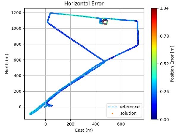
The effect of this fusion strategy is illustrated in Figure 13, which shows the estimated trajectory compared with the reference path. The horizontal error is visualized with a colour scale ranging from the minimum up to the 95th percentile. The results indicate that the fused position remains within approximately 20 cm across most of the urban trajectory, including sections with partial GNSS degradation due to vegetation, obstructed open-sky conditions, and when crossing bridges. In the outdoor part of the trajectory, the fused solution relies primarily on the tightly coupled GNSS–IMU subsystem. In contrast, when entering fully GNSS-denied environments such as the indoor parking area, the filter shifts its reliance to the LiDAR- and vision-based
subsystems, which play a key role in sustaining localization. In the indoor parking facility, where the vehicle performed three loops over roughly three minutes with no GNSS availability, the error increased up to about 1m.
The indoor sections of the trajectory represent the most challenging and therefore the most relevant part of this study. As described earlier, the LiDAR- and visual-based filters are integrated into the central filter using a stochastic cloning strategy. This means that their positions are not fused in an absolute sense but rather in a relative manner, so the accumulated drift before entering the parking lot does not affect the fusion outcome. What truly matters is the ability of these subsystems to consistently follow the reference trajectory while GNSS is completely unavailable.
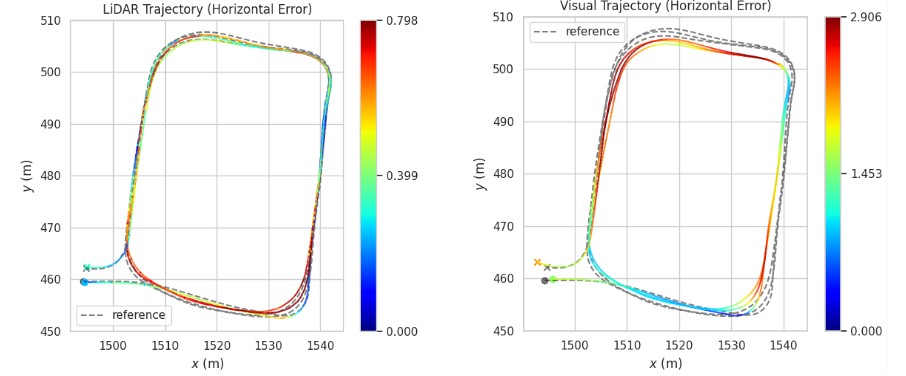
Figure 14 illustrates the trajectories estimated by the LiDAR-based (left) and visual-based (right) filters, covering the segment from just before entering the underground parking facility until exiting it. This is precisely the region where these subsystems have the most influence on the central filter estimate. The LiDAR-based solution demonstrates good consistency, with horizontal errors remaining below 0.8 m across the three loops. By contrast, the trajectory obtained by visual localization in a globally optimized map where dynamic object were removed exhibits a larger error growing up to ~3 m during the same period.
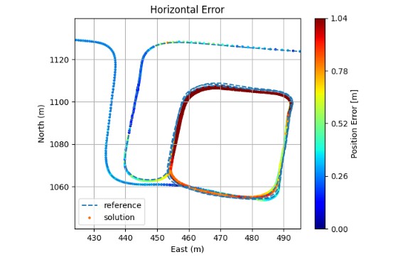
The central filter performance in the indoor section, including the transitions when entering and exiting the parking facility, is shown in Figure 15. As previously discussed, the fusion logic weights each subsystem according to its reported uncertainty. Consequently, inside the parking area the solution relies mainly on the LiDAR SLAM subsystem, which demonstrates stable and accurate behaviour under GNSS-denied conditions, while the visual odometry contribution is down-weighted due to its higher drift. At the same time, the IMU plays a key role in the prediction step of the filter. The system enters the parking area with a well-converged solution, where biases have been properly calibrated. This, together with a well-defined prediction model,
ensures that IMU propagation maintains a stable and bounded trajectory estimate over the entire indoor segment.
Another relevant outcome illustrated in this figure is the smooth transition behaviour at both the entrance and exit of the parking area. No discontinuities or jumps are observed in the estimated trajectory, particularly at the exit, when the geo-referenced GNSS solution becomes available again. This indicates that no major cumulative drift is added during the indoor phase; otherwise, a sudden correction would be visible once the GNSS-based position is recovered.
CONCLUSIONS AND NEXT STEPS
This work has presented an AI-enhanced multi-sensor fusion framework for autonomous vehicle navigation, combining GNSS, IMU, and LiDAR/visual SLAM subsystems within a federated Kalman filter. A key outcome is the systematic integration of AI across all three components, targeting specific performance criteria such as accuracy, availability, integrity, and robustness.
Importantly, this study goes beyond a proof of concept. The system has been designed, optimized, and verified to ensure operational feasibility under real-world constraints. All algorithms run in real time on embedded automotive-grade hardware, demonstrating that the approach is suitable for deployment on resource-constrained platforms.
At the perception level, the AI networks developed for dynamic object detection and removal have been shown capable of operating in real time on both camera and LiDAR inputs. By filtering out moving features, they improve the robustness and accuracy of SLAM-based localization in dense urban environments.
At the inertial level, a Multitask Deep Neural Network was introduced to jointly learn IMU calibration, adaptive noise estimation for non-holonomic constraints, and zero-velocity detection directly from raw IMU signals. This improves the prediction performance in situations where the position estimate relies primarily on the IMU.
At GNSS level, we developed a neural network for interference detection. Using datasets collected during the JammerTest 2024 campaign, the system was trained and validated to distinguish legitimate satellite signals from jamming, spoofing, and meaconing attacks. A key strength of the approach is that the network not only detects the presence of interference but also provides specific information on the signals and satellites affected. This enables mitigation actions that minimize the impact on availability and accuracy, rather than requiring broad rejection of measurements.
The end-to-end solution, combining all sensor inputs, AI-based enhancements, and multi-sensor fusion techniques, has been tested in a challenging urban scenario including multipath conditions, GNSS-degraded areas and indoor conditions. Results demonstrate that the central filter maintains high-accuracy performance (decimetre level in most conditions) and robustness, with bounded errors even in fully GNSS-denied environments such as indoor parking facilities.
Looking ahead, one of the key research directions is to enhance the accuracy of LiDAR- and visual-based localization. To this end, we are already working on the generation of high-accuracy geo-referenced maps that can later be exploited for online re-localization. The idea is to build these maps offline using more powerful computational resources, advanced optimization techniques such as RTS forward–backward filtering, and even additional sensors not available in the online configuration. The resulting HD maps—including LiDAR and visual features geo-referenced to GNSS—are then uploaded to the embedded
platform. During online operation, these maps can be used by the localization modules to refine the solution, improving accuracy and robustness, and potentially providing absolute position estimates (rather than relative ones) when revisiting already mapped areas.
In parallel, as part of the DREAM project, we are also working on perception-oriented modules to automatically detect, classify, and track road users (e.g., cars, pedestrians, bicycles) using 3D bounding boxes, along with the detection of traffic lights and their current state. Another outcome of the project will be the generation of 2D maps with lane-level information, enriched with semantic data such as driving direction, traffic lights and signals. These new localization, perception and mapping features will be progressively integrated into our ANavS product portfolio in the coming months.
ACKNOWLEDGMENTS
The authors would like to express their sincere gratitude to the European Union and the European Union Agency for the Space Programme (EUSPA) for funding the DREAM project under the Fundamental Elements programme, and for their valuable guidance and support throughout the project.
Disclaimer: Views and opinions expressed are, however, those of the authors only and do not necessarily reflect those of the European Union or the EUSPA. Neither the European Union nor the EUSPA can be held responsible for them.
REFERENCES
- S. I. Roumeliotis and J. W. Burdick, (2022). Stochastic cloning: a generalized framework for processing relative state measurements. Proceedings 2002 IEEE International Conference on Robotics and Automation (Cat. No.02CH37292), Washington, DC, USA, 2002, pp. 1788-1795 vol.2, doi: 10.1109/ROBOT.2002.101480
- P. Bohlig, et al. (2025), Detection and Mitigation of Jamming, Meaconing, and Spoofing based on Machine Learning and Multi-Sensor Data. ION GNSS+ 2025.
- F. Schmid and J. Fischer, (2025). Multitask Deep Neural Network for IMU Calibration, Denoising and Dynamic Noise Adaption for Vehicle Navigation. European Navigation Conference 2025.
- L. Sachße, et al., (2025). Robust real-time automotive Visual SLAM with dynamic object removal. European
Navigation Conference 2025. - P. J. G. Teunissen, (1995). The least-squares ambiguity decorrelation adjustment: A method for fast GPS integer ambiguity estimation. Journal of Geodesy, vol. 70, no. 1–2, pp. 65–82, 1995.
- T. Ozeki and N. Kubo, (2022). GNSS NLOS signal classification based on machine learning and pseudorange residual check. Frontiers in Robotics and AI, vol. 9, May 2022.
- S. Parimi and R. Bensch, (2025). Edge Device-Optimized LiDAR SLAM for Real-Time and Robust Localization in Dynamic Environments. ION GNSS+ 2025.
- Xu, W., Cai, Y., He, D., Lin, J., and Zhang, F. (2021). FAST-LIO2: Fast direct lidar-inertial odometry.