Tightly Coupled Sensor Fusion with Artificial Intelligence (AI)
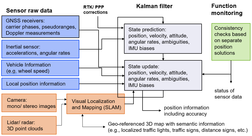
A tight coupling fuses the GNSS, INS and wheel odometry raw measurements (instead of individual position solutions). It is typically performed with an (extended) Kalman filter. The state vector of unknowns includes the position, velocity, attitude (in terms of quaternion), acceleration bias, and ambiguities. The Kalman filter consists of two steps: a state prediction and a state update. The state prediction uses either a movement model or alternatively directly the IMU measurements. For the latter case, the prediction of the quaternion uses the angular rate measurements (provided in a body-fixed frame). This is a non-linear operation. The covariance matrix of the predicted states follows from the law of error propagation and is determined by linearization of the state prediction with respect to the states and IMU measurements. The subsequent state update is performed with the GNSS measurements or measurements from other sensors (e.g. wheel odometry, barometer, or pose information obtained from camera or Lidar SLAM). The state update determines the innovation (being the difference between the actual GNSS measurements and computed GNSS measurements based on the predicted states), projects the innovation with the Kalman gain into the state domain and applies the respective correction to the predicted states. The covariance matrix is updated accordingly. As the Kalman gain is determined such that the variance of the updated states is minimised, the state update typically reduces the uncertainty of the state estimates.

Applications of tightly coupled sensor fusion with AI
The accuracy and reliability of positioning with a Global Navigation Satellite System (GNSS) is highly dependent on the environmental conditions. By now, maximum position accuracy in combination with fast convergence is obtained with Real-time kinematic (RTK) positioning under favourable open sky conditions where a position error at centimetre-level can be reached. The use of RTK, however, is restricted to the area spanned by the local network of RTK reference stations. A more versatile method is Precise Point Positioning (PPP) which takes advantage of precise orbit, clock and bias corrections estimated by a global network of reference stations. The advantages and disadvantages of both methods are given in Table 1.
|
|
Advantage |
Disadvantage |
|
RTK |
– Fast convergence – Highest accuracy due to the fixing of the phase ambiguities to integer. |
– Limited to the coverage of the RTK reference station ( radius) |
|
PPP |
– Corrections are (almost) globally valid – High accuracy |
– Long convergence time – Fixing of phase ambiguities is often not feasible due to residual biases |
Table 1: Advantages and disadvantages of RTK and PPP.
With the development of autonomous vehicles, the demand for a reliable and accurate position becomes more and more important. Furthermore, it is not only needed under favourable conditions, but also requested in harsh environment to make autonomous driving in challenging suburban and urban areas possible.
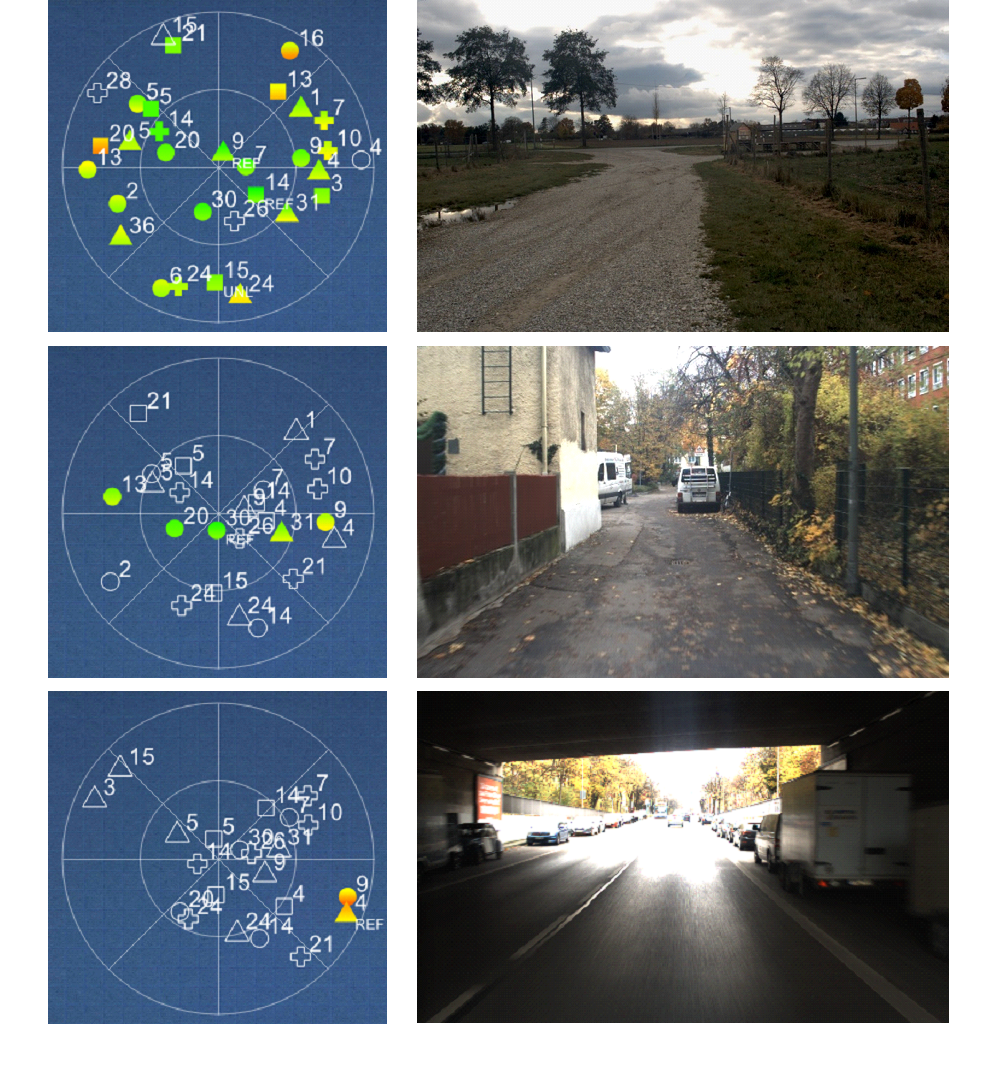
The figure below shows three examples of environmental situations which are likely to be faced during a drive through rural, suburban, and urban areas. The first example at the top shows very favourable conditions of GNSS signal reception. There are barely any obstacles which shadows the GNSS signals or introduce multipath. This is also visualized by the corresponding sky plot, which shows many tracked signals and a high carrier-to-noise density ratio. In the second example, a challenging area is passed, where buildings and trees are very close to the street. Signals of satellites with a low elevation are therefore blocked by the surrounded buildings and trees. Only satellites along the street and with a high elevation are visible and can be tracked reliably, which is also visualized by the sky plot. In the last example an almost complete outage of the GNSS signals is observed when passing a bridge. Only two satellites were still trackable by the receiver. These signals coming from one opening of the bridge and are thus from satellites with a low elevation and furthermore of poor-quality regarding the signal strength and multipath.

In these challenging situations the use of additional sensors is inevitable to maintain a high accuracy of the position. Several sensors used for the fusion with GNSS are described in Table 2, where advantages and disadvantages for each sensor are summarized and complementary.
Table 2: Advantages and disadvantages of each sensor.
|
|
Advantage |
Disadvantage |
|
IMU |
– Completely independent on the environment, and thus very high availability |
– No absolute position – Estimation of biases necessary |
|
Odometry |
– Highly accurate velocity measurement – Does not dependent on the environment except the ground |
– Often only the absolute value is provided by the interface of the vehicle – Wheel slip can occur for certain terrains |
|
Lidar |
– Provides a position estimate especially in challenging environment where many objects can be tracked – High accuracy with loop closures |
– Additional effort for the map generation – Estimation of the transformation between Lidar and GNSS frame necessary. |
|
Camera |
– Provides velocity and angular rates by visual odometry especially in challenging environment where many objects can be tracked |
– High latency – More inaccurate than IMU (angular rates) + odometry (velocity) |
Tightly Coupled RTK/PPP Products of ANavS®
ANavS® is offering several products for PPP positioning:
Multi-Sensor RTK/PPP module – our standard solution for PPP and RTK (with handover between both techniques) positioning with a tight coupling of GNSS, INS and wheel odometry.
The Integrated Sensor Platform (ISP) – our solution for the most demanding applications. It includes 3 GNSS receivers, an inertial sensor, a wheel odometry interface, 2 cameras, a 3D LiDAR and a very powerful sensor fusion. It is the ideal solution for Autonomous Driving.