Precise Positioning for Autonomous Driving in both Indoor and Outdoor Environments
Patrick Henkel, Sai Parimi, Jan Fischer, Ulrich Mittmann and Robert Bensch, ANavS GmbH
BIOGRAPHY
Patrick Henkel is the founder and managing director of ANavS and a senior lecturer at the Technical University of Munich (TUM), Germany. His research interests include all aspects of precise and reliable positioning. He led the design of the reference PPP user algorithm for Galileo’s new High Accuracy Service (HAS). He was a guest researcher at TU Delft in 2007, at the GPS Lab at Stanford University in 2008 and 2010, and at Curtin University in 2013. He received the Dissertation Award (2011) of the Vodafone Research Foundation for his PhD thesis on Precise Carrier Phase Positioning and was a Regional Winner in the European Satellite Navigation Competition (2010).
Sai Parimi is a computer vision expert at ANavS GmbH. He works mainly on environment perception using LiDARs with a major focus on LiDAR SLAM and 3D object detection. He received his M.Sc. degree in Electrical and Computer Science Engineering from Darmstadt Univerity of Applied Sciences, Germany. He graduated in 2021 with a masters thesis from Fraunhofer-Institut f¨ur Produktionstechnik und Automatisierung working on real-time point cloud segmentation for industrial object detection to improve bin picking robot’s sorting algorithm. He has been working at ANavS GmbH since 2022.
Jan Fischer completed his master’s degree in Mechatronics and Information Technology at the Karlsruhe Institute of Technology. In his master thesis at Fraunhofer IOSB, he developed an efficient multi-task deep learning architecture for person re-identification and attribute recognition. Since 2022 he has been working as a computer vision and data fusion engineer at ANavS GmbH. His main focus at ANavS is the Visual SLAM and Multi-Sensor RTK system.
Ulrich Mittmann completed his apprenticeship in energy electronics at KraussMaffei Group GmbH. He studied at the University of Applied Sciences in Munich, Germany, and received his B.Sc. and M.Sc. in Electrical Engineering and Information Technology from the Technische Universit¨at M¨unchen. In his master’s thesis he investigated the GLONASS integer ambiguity resolution for RTK positioning. Since 2016, he is working for ANavS as algorithm and software developer on Multi-Sensor RTK positioning.
Robert Bensch leads the computer vision team at ANavS. The team focus is on precise and robust positioning in GNSS denied or degraded areas and the environment detection using camera and LiDAR sensors. He received his PhD degree in applied computer science from the Albert-Ludwigs-Universit¨at Freiburg, Germany, with focus on biomedical image analysis and motion pattern analysis. He contributed to the study of biological signalling processes. Dr. Bensch joined ANavS in 2017 and has been building up the computer vision team since several years
ABSTRACT
Autonomous operations are very attractive at factory and storage premises as they reduce personnel costs and as they require the meeting of less strict standards and norms than the public road sector. However, autonomous operations at factory and storage premises are quite challenging for precise positioning as they include both indoor and outdoor operations. More specifically, high quality GNSS signal reception is limited to outdoor environments. Moreover, metallic walls and/ or doors cause severe multipath errors. LiDAR and Camera SLAM can provide an accurate indoor positioning solution, but the movement from indoor to outdoor as well as from outdoor to indoor remains challenging due to under-/ overexposure of the camera during the indoor/ outdoor transitions.
Our solution to this problem includes a very powerful sensor fusion of GNSS RTK/ PPP, inertial, wheel odometry, camera and LiDAR sensors. The raw measurements of the first three sensors (GNSS, IMU, wheel odometry) are tightly coupled in an extended Kalman filter. The raw data (pixels and point clouds) of the visual sensors (camera, LiDAR) are pre-processed in a SLAM and the obtained pose information is then used in the extended Kalman filter. The main objective of the visual sensors is to enable a drift-free positioning in indoor areas without GNSS signal reception. Obviously, the sensor fusion combines the measurements from all 5 sensors, but the main driver of the accuracy depends on the area: Outdoor, the highest accuracy is given by the GNSS RTK/ PPP solution. Indoor, the highest accuracy is achieved by the LiDAR/ camera SLAM. In the indoor/outdoor transition area, the most reliable position sensors are INS and wheel odometry.
1. INTRODUCTION
Autonomous driving is very attractive for vehicles and robots in logistics, e.g. for transportation of goods from goods receipt points to storage shelves and vice versa, or for the transportation of goods from storage shelves to customer pick-up points. Autonomous driving requires precise positioning, object determination and tracking, trajectory planning, maneuver planning, and fleet management. There is a need for precise positioning both indoor and outdoor. Factory traffic runs typically on both public roads and private factory premises.
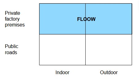
We target both indoor and outdoor operations on private factory premises in the project FLOOW as shown in Fig. 1. The scope of the project FLOOW is the development of a flexible mobility and cargo system for factory works.
II. METHODOLOGY
1. Sensor Fusion Architecture for Precise Positioning
Fig. 2 provides an overview of our architecture for precise positioning.
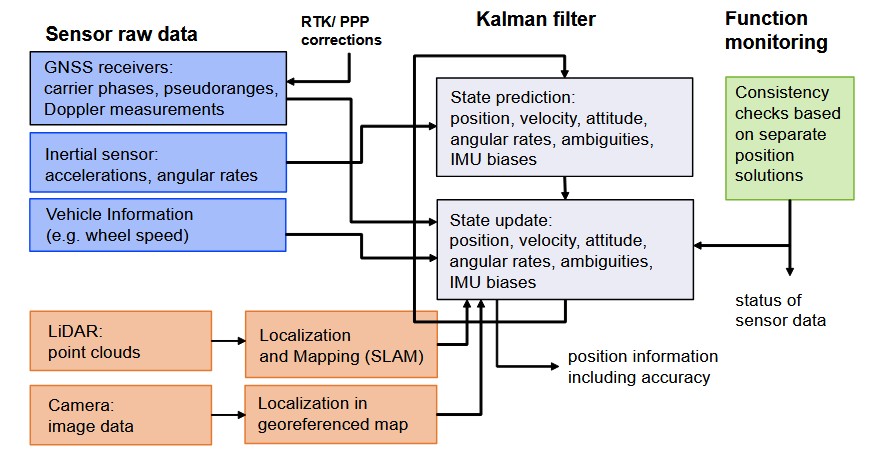
We use an extended Kalman filter for the sensor fusion. For a detailed description of the Kalman filter, we refer to the famous textbook of Brown and Hwang (2012). The raw GNSS pseudorange, carrier phase and Doppler measurements, the acceleration and angular rate measurements of the inertial sensor, and the wheel speed measurements of the odometer are tightly coupled in the extended Kalman filter. RTK/ PPP corrections are applied to the raw GNSS measurements (i.e. before the sensor fusion) to further improve the accuracy of the solution. For a more detailed description of our RTK and PPP solution, we refer to our earlier publications, see Henkel and Iafrancesco (2014), Henkel and Sperl (2016) and Pintor et al. (2022). The inertial sensor measurements are used for the state prediction and the GNSS and odometer measurements are used for the state update in the Kalman filter. The estimated state parameters include the position, velocity, acceleration, attitude (expressed by quaternion), the quaternion rate, the carrier phase integer ambiguities, and the accelerometer and gyroscope measurement biases.
The LiDAR raw point cloud data are pre-processed in a Simultaneous Localization and Mapping (SLAM). The obtained position and attitude information is then loosely-coupled within the extended Kalman filter. The camera raw data are also pre-processed including a projection from the camera’s perspective to bird-eye view and a feature extraction. The visual positioning also uses a geo-referenced map. The relevant part of the map is selected based on the current position solution. Subsequently, feature points are determined in this relevant part of the map. The feature points of the projected camera image are matched with the feature points of the map. This feature matching provides an information on the position offset between the position estimate related to the camera/ vehicle and the position related to the accurate map. The transformation (translation and eventually also rotation) is determined using the position offsets from all feature points. The application of this transformation to the camera-based position leads to an improved position, which is then used in the extended Kalman filter. Our system architecture also includes a functional monitoring. More specifically, we estimate a separate position solution and covariance matrix for each sensor. Subsequently, we check the consistency of the solutions from all sensors by verifying, whether the error ellipsoids from all sensors are intersecting. We refer to our earlier paper for a more detailed mathematical description of this method (Henkel et al. (2023)). If the error ellipsoids of all sensors are intersecting in at least one point, the measurements of all sensors can be fused. If this is not the case, the covariance matrices are scaled until an intersection is achieved. Subsequently, the sensor fusion is performed.
2. LiDAR based Localization and Mapping
In the recent times, a lot of research is being carried out in the field of LiDAR SLAM (Simultaneous Localization and Mapping) for autonomous driving to take advantage of the fact that LiDARs are very robust sensors that work great in various environments and can offer a 360◦ horizontal field of view which helps to improve feature extraction and, thereby, providing more precise poses. Currently, there are multiple LiDAR sensors varying from the cheaper 2D LiDARs to costlier 3D LiDARs. Since the range of a 2D LiDAR sensor is usually not that high (∼20m), it is mainly used for indoor SLAM. 3D LiDARs are used for outdoor SLAM since they offer much higher ranges (varying between 100m to 200m) and relatively denser point clouds as compared to a 2D LiDAR.
Due to its compact size, a 2D LiDAR is preferred for indoor robots to perform SLAM since it reduces the overall size of the robot and therefore increases its maneuverability indoors. In 2D SLAM often an occupancy grid map is chosen as the map representation, which is a probabilistic map of the environment represented by a series of binary random variables. These random variables represent the presence of an obstacle at their corresponding location in the map. Some of the widely used 2D SLAM approaches like Hector SLAM (Saat et al. (2020)), GMapping (Grisetti et al. (2007)) and Cartographer from Google (Hess et al. (2016)) all have good performance, especially for our use case where real-time performance on an embedded platform, like NVIDIA Jetson, is required. A detailed comparison of these approaches (Sandoval-Castro et al. (2020)) shows that Cartographer is slightly more robust and precise in terms of re-localization. Considering the working environments and operating speeds of such robots, usually, just a LiDAR sensor is sufficient for SLAM.
SLAM for mobile outdoor robots, such as autonomous cars, requires LiDAR sensors which have a much larger range and generate denser point clouds since the obstacles outdoors are not as clustered as the indoor environment and potentially much further away. Outdoor environments usually have more dynamic obstacles and robots are driving much faster than their indoor counterparts, such that relying only on LiDAR sensors for SLAM may lead to huge drifts or even more severe errors. To overcome this, the LiDAR sensor is usually coupled with an IMU to perform LiDAR-Inertial based Localization and Mapping. Some of the popular 3D LiDAR SLAM approaches, such as LOAM (Zhang and Singh (2014)) or LeGO-LOAM (Shan and Englot (2018)), are loosely coupled SLAM approaches where the IMU is only used in the frontend for de-skewing the point clouds and to provide a motion prior to scan matching. Although such loosely coupled systems are lighter and use lesser
resources, they are not very robust. For a more robust system, we tightly couple the LiDAR and IMU measurements wherein, the IMU is not only used in the frontend for de-skewing, but also in the backend for optimization. The localization and mapping processes work simultaneously using each others outputs for a precise pose estimation. We are making use of a tightly coupled LiDAR-Inertial SLAM approach, LIO-SAM (Shan et al. (2020)), which, in the backend, makes use of factor graphs and the optimization of the factor graphs is done with the help of incremental smoothing and mapping with Bayes tree (Kaess et al. (2011)).
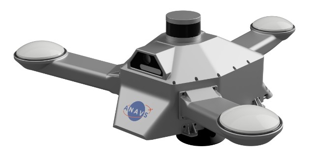
3. Integrated Sensor Platform
ANavS has developed an Integrated Sensor Platform (ISP) that we used for recording the raw data. The ISP includes 3 multi-frequency GNSS antennas and receivers, an IMU, a CAN odometer interface, two cameras, a 3D LiDAR, two NVIDIA boards for the processing of the camera and LiDAR data, an ARM processor for the GNSS/ INS/ odometer based tightly coupled sensor fusion, and an LTE module for obtaining RTK/ PPP corrections. The advantage of the ISP is that it includes all sensors in a single platform, and thereby, the user does not need to cable each sensor individually. Moreover, the user does not need to determine the lever-arms between the sensors as they are already known by the system.
The sensors are also synchronized internally, which makes the further data processing also convenient for the user.
3. Results
In this section, we present our results for precise positioning.
1. GNSS RTK/ PPP + INS + odometer
We perform a joint position and attitude determination with an extended Kalman filter. IMU measurements are used for the state prediction. GNSS and odometer measurements are used in this subsection for the state update, i.e. no LiDAR and camera data are used. The positioning accuracy is improved by using RTK/ PPP corrections and by additionally resolving the carrier phase ambiguities to integer numbers.
The Integrated Sensor Platform (ISP) includes one geodetic-quality GNSS receiver (MOSAIC X5 chip from Septentrio) and two additional automotive-grade, dual-frequency GNSS receivers (ZED-F9P chips from u-blox). The MG-370 IMU from Epson is used within the ISP. The IMU has a bias stability of 0.8◦ per hour for the gyroscope and of 0.01 mg for the accelerometer. The RT 3000 from OXTS is considered as ground truth as it is widely used in the automotive industry. However, it is doubtful if it can really serve as ground truth since it is also based on the same sensor technologies (GNSS and IMU) and since its performance is not significantly better than the ANavS solution.
2. LiDAR SLAM
The results group into two scenarios: the first one is a warehouse scenario including localization and mapping indoor, outdoor and at the transition between indoor and outdoor. The second scenario corresponds to an indoor scenario in a parking garage. For both scenarios the Integrated Sensor Platform including its 3D LiDAR sensor has been used. For the parking garage scenario, a laser scanner-based ground truth was available. For the warehouse scenario, outdoor an RTK-fixed solution was used as a reference. Indoor, the repeatability was demonstrated by repeatedly approaching position markers on the ground in several rounds.
a) 2D Occupancy Grid-Based LiDAR SLAM
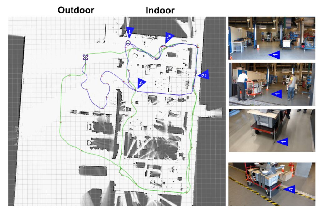
A 2D occupancy grid-based LiDAR SLAM approach has been applied for the warehouse scenario, as introduced in Section II. For this purpose the 3D LiDAR scans have been projected to 2D scans first to be applicable for 2D SLAM. Fig. 6 illustrates the detailed 2D occupancy grid map that was generated during the two runs indicated by the blue and the green trajectory. The occupancy map shows free areas in white and occupied areas in black, while unknown areas are shown in gray. The map accurately represents both the indoor environment (on the right side) and the outdoor area (on the left side). In this setup the Integrated Sensor Platform was mounted on an industrial trolley and pushed manually. The two motion trajectories that are estimated from SLAM along with the occupancy map are illustrated in Fig. 6 (trajectories in blue and in green) and analyzed in more detail in the following. During the runs several position markers (marked on the ground) have been repeatedly approached
to demonstrate repeatability and accuracy of the solution. Fig. 6 shows the locations of the markers (1-4) and provides some sample pictures of the scene.
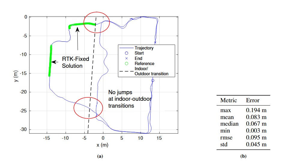
Fig. 7, which refers to the green trajectory plotted in Fig. 6, provides a quantitative analysis of the LiDAR positioning accuracy in the outdoor area of the warehouse. A GNSS-based RTK-fixed position solution was generated for the outdoor area and compared to the pose trajectory estimated by 2D LiDAR SLAM, which yields a median error of 6.7cm in the overlapping range with the RTK-fixed solution, shown in green in Fig. 7a, further error metrics are given in 7b. Besides these results, an overall smooth position solution both indoor and outdoor can be observed, as well as smooth indoor-outdoor transitions without jumps. The indoor-outdoor transition is depicted by a dashed line in the figure.
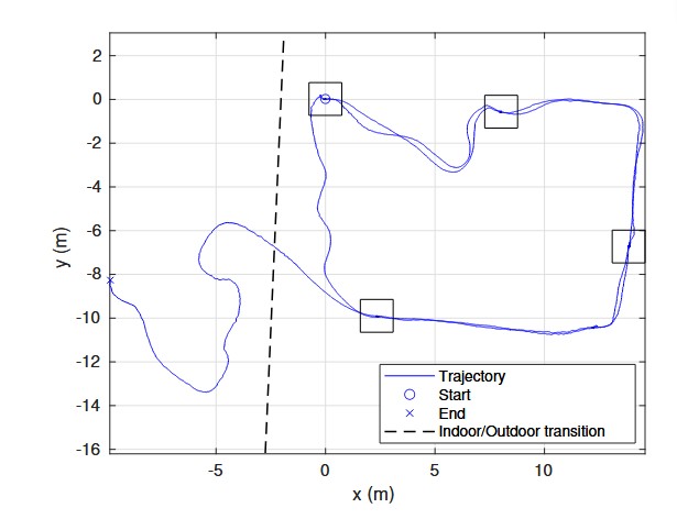
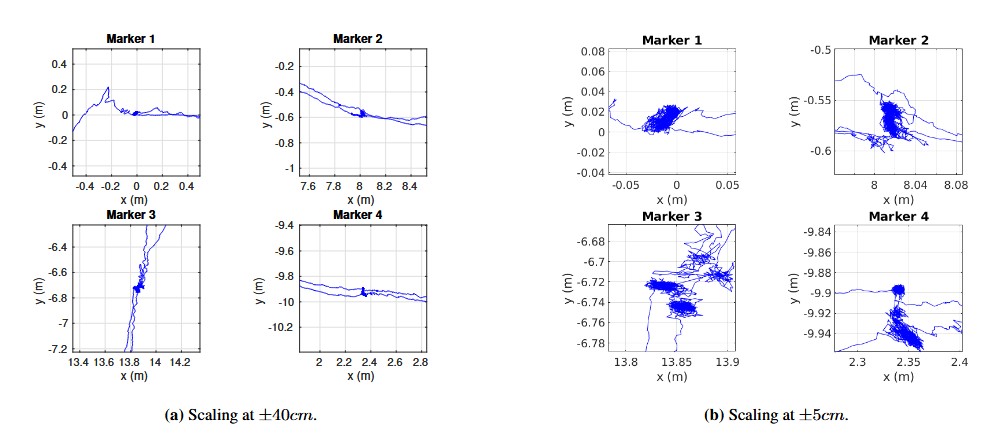
In Fig. 8, which refers to the blue trajectory plotted in Fig. 6, another trajectory result is shown. It is generated by the 2D LiDAR SLAM. The trajectory shows a smooth path of the tracked motion both indoor and outdoor, as well as across the indoor-outdoor transition. Furthermore, the trajectories of two rounds along the narrow corridors on the right side and on the bottom lie on each other very well. Moreover, in this run several position markers on the ground have been repeatedly approached. These four locations are marked in the Fig. 8 by rectangular shapes and analyzed in more detail in the following Fig. 9.
Fig. 9 provides close up views of the trajectories at the four locations that have been approached twice in the respective run. These results show on the one hand a high localization accuracy with low noise of the position estimate at static locations, and on the other hand a high degree of reproducibility, since localization estimates fall very close to each other for the repeated visits of each marker in each round (clusters indicate noisy location estimate in steady states when markers are approached)
b) 3D Point Cloud Based LiDAR SLAM
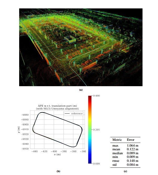
For the parking garage scenario considered in results Fig. 10 a point cloud based 3D LiDAR SLAM approach has been applied,as introduced in Section II. For this purpose the 3D LiDAR scans have been used directly together with inertial measurements from an IMU. The Integrated Sensor Platform was mounted on a measurement vehicle which performed an indoor round inside a parking garage three times repeatedly. The obtained detailed 3D point cloud of the indoor environment is shows in Fig. 10a. The regular spaced concrete pillars, larger concrete shafts and parked cars can be observed well in the point cloud. The point cloud is color-coded by the reflective intensity showing concrete and vehicle parts in different colors, for example. Fig. 10a shows the estimated 3D trajectory of the vehicles motion as well (in cyan), which is compared against a laser scanner-based reference in Fig. 10b and c. Fig. 10b provides a top-view of the three rounds estimated trajectory against the reference. The trajectory of the three rounds, as well as the reference trajectory can hardly be distinguished because they nearly fall onto each other. The trajectory is color-coded by the residual error which varies along the round cycles between 0.9cm and ≈ 40cm. The error metric are given in Fig. 10c.
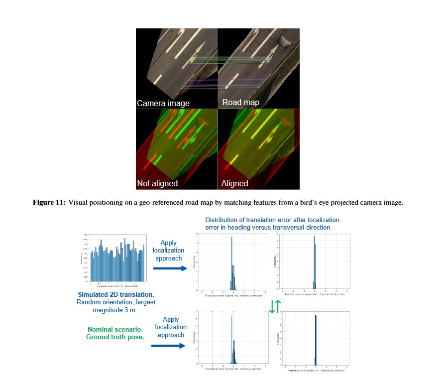
3. Visual Positioning on a Geo-Referenced Road Map
This approach assumes a precise geo-referenced road map given for the area of interest (see Fig. 11). The road map consists of geo-referenced RGB image tiles which include a pixel wise weight mask to down-weight or exclude areas that are not mapped for example. The generation of such a precise road map shall not be in focus of this article. Visual localization in this approach is based on a given estimate of the global position and attitude, obtained from the GNSS-based solution. Using an image observation from a monocular camera mounted on the vehicle, the global position and attitude can be corrected by matching against the geo-referenced road map.
The camera image is first projected to bird’s eye view. Second, the projected camera image is aligned to the attitude direction by 2D rotation. In a third step, the corresponding map tile image is retrieved using the given global position. Based on the
projected, aligned camera image and the retrieved map tile image feature matching is performed between this pair of images. Fig. 11, top row, gives an example of such a pair of projected and rotated camera image and retrieved map tile image. Goal of the feature matching is to estimate good feature correspondences and based on these the transformation that best aligns the camera image to the map. Assuming a precise prior information of the attitude, we restrict the algorithm to estimate a 2D translation only.
Feature matching in this implementation is based on a classical feature matching pipeline. Images are first normalized by their minimum and maximum intensity, and image and mask borders are handled, such that no artificial features are detected at these borders. For computing image feature detections and corresponding descriptors the A-KAZE local features detector is used as described in Alcantarilla et al. (2013). The image pair is rejected if the number of detected features in one of the two images
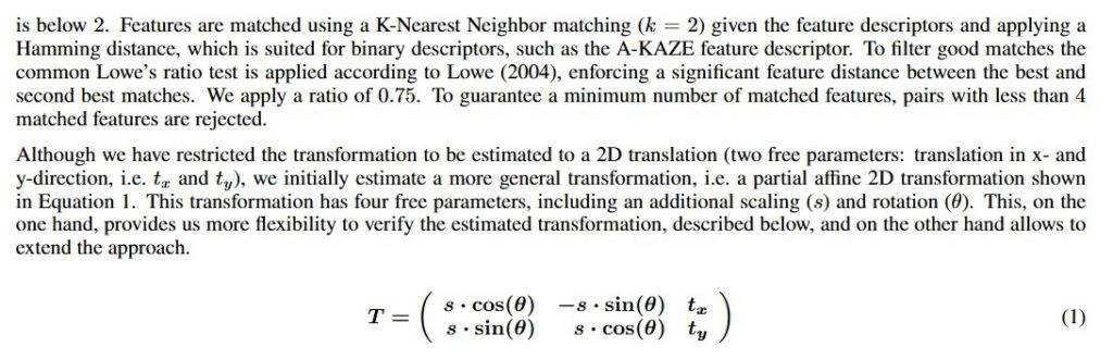
We use the builtin function „estimateAffinePartial2D“ from the OpenCV library, refer to Bradski (2000)), to estimate the parameters, which includes a RANSAC approach and returns the number of inliers used for estimation. We reject results with less than 4 inliers. To obtain the final estimate for the 2D translation, we re-estimate the translation from the inliers. Fig. 11, top row, shows an example of successful inlier matches from the camera image to the map, as well as the final results when overlaying the transformed (shifted) camera image to the map (RGB-overlay in the bottom right image).
Several verification steps are added to further reject potential outliers. A local intensity-based template matching is performed based on the 2D correlation function between the image and the map. The transformation is rejected if no local maximum is detected within a predefined radius of 15cm. In addition the estimated scaling and rotation parameters are checked and lead to rejection if they are deviating too much from the expected parameters. Transformations that are accepted provide a correction to the initial GNSS-based position through the estimated 2D translation.
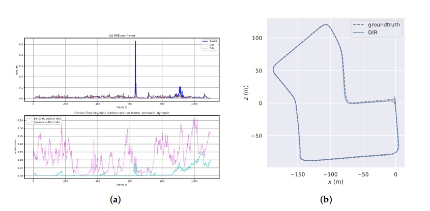
The feature matching approach was validated by simulating 2D displacements with a maximum magnitude of 3m. The results depicted in Fig. 12 show that the simulated displacements can be compensated effectively by the approach (residual error histograms) and that the results are comparable to the nominal case when applying the ground truth poses with no simulated displacements added. Furthermore, the results suggest a larger error in the heading direction, compared to the transversal direction, which is natural and correlated with the direction of viewing/ motion. Time-synchronization errors have a stronger impact in motion direction as well.
3.4. Real-time setup
For online usage, all components of the proposed system were implemented in the ROS2 framework [ 20] with the aim of deployment in a real vehicle for real-time applications. The used Car PC is equipped with an Intel Core i9-13900E CPU and an NVIDIA RTX 4080 Super 16 GB GPU. For test purposes, the KITTI Odometry sequences were converted to ROS2 bag files.
The GPU-accelerated Mask R-CNN model was able to reach up to 48 fps performance on the given setup, exceeding the 10 fps data rate of the KITTI Odometry dataset and fulfilling the common real-time processing requirement of 30 fps.
The generation and processing of segmentation masks leads to a latency of 21 milliseconds in the processing pipeline, which the Visual Odometry solution has to wait. To reduce this latency we applied the mask propagation approach from Section 2.2 which reduced the latency to 14 milliseconds on average. For usage on less powerful computers
and embedded systems, application of the mask propagation algorithm becomes crucial, because instance segmentation networks run at less than 5 frames per second.
IV. DISCUSSION AND CONCLUSIONS
In this paper, we have presented an integrated sensor platform with 3 multi-frequency GNSS receivers, an IMU, a CAN interface for odometry data, 2 cameras, a 3D LiDAR and a powerful sensor fusion for precise position and attitude determination. The
GNSS, IMU and odometry measurements are tightly coupled, and the LiDAR and camera based position information is loosely coupled within the Kalman filter.
GNSS RTK can provide centimeter-level positioning accuracy outdoors. Short GNSS outages can be overcome with odometry and IMU measurements. LiDAR based SLAM and visual positioning with a camera and a geo-referenced map can support precise positioning outdoors, too. The only need is to have sufficient textures in the close-by environments, which should not be a real limitation for factory premises. Less textures typically means more open sky conditions and, thus, better satellite visibility. Vice versa, less satellite visibility means more obstacles and, thus, more features for visual positioning. Thereby, GNSS and LiDAR/ camera are complementing each other very well. The LiDAR SLAM can provide centimeter-level accuracy for indoor positioning.
IMU measurements can be integrated within the LiDAR SLAM to predict the motion and feature points, and thereby, enhance the performance. Multipath and over-/ underexposure of camera images might temporarily reduce the positioning accuracy at
the indoor/ outdoor as well as outdoor/ indoor transition. However, this issue could be overcome with inertial and odometry measurements and, thereby, provide a seamless position information in almost any environment.
ACKNOWLEDGEMENTS
The authors would like to thank the German Federal Ministry for Economics and Climate Action (BMWK) for a grant to the project ”FLOOW” (grant number: 19A20025A), in which ANavS develops precise position and environment detection methods for both indoor and outdoor environments.
REFERENCES
Alcantarilla, P. F., Nuevo, J., and Bartoli, A. (2013). Fast explicit diffusion for accelerated features in nonlinear scale spaces. In Burghardt, T., Damen, D., Mayol-Cuevas, W. W., and Mirmehdi, M., editors, British Machine Vision Conference, BMVC 2013, Bristol, UK, September 9-13, 2013. BMVA Press.
Bradski, G. (2000). The OpenCV Library. Dr. Dobb’s Journal of Software Tools.
Brown, R. and Hwang, P. (2012). Introduction to Random Signals and Applied Kalman Filtering with Matlab Exercises. Wiley, New York.
Grisetti, G., Stachniss, C., and Burgard, W. (2007). Improved Techniques for Grid Mapping with Rao-Blackwellized Particle Filters. IEEE Transactions on Robotics, 23(1):34–46.
Henkel, P., Horwath, M., and Sachsse, L. (2023). Intersection of Error Ellipsoids from at Least Two Positioning Sensors for Improved Sensor Fusion. In ION Proc. of Intern. Technical Meeting (ITM), pages 1110–1117, Long Beach, CA, USA.
Henkel, P. and Iafrancesco, M. (2014). Tightly coupled Position and Attitude Determination with two low-cost GNSS receivers. In IEEE Proc. of 11-th Intern. Symp. on Wireless Communication Systems (ISWCS), pages 895–900, Barcelona, Spain.
Henkel, P. and Sperl, A. (2016). Precise RTK Positioning with GPS/ INS Tight Coupling and Multipath Estimation. In ION Proc. of ION International Technical Meeting (ITM), pages 1015–1023, Monterey, CA, USA.
Hess, W., Kohler, D., Rapp, H., and Andor, D. (2016). Real-time loop closure in 2d lidar slam. In 2016 IEEE International Conference on Robotics and Automation (ICRA), pages 1271–1278.
Kaess, M., Johannsson, H., Roberts, R., Ila, V., Leonard, J., and Dellaert, F. (2011). isam2: Incremental smoothing and mapping with fluid relinearization and incremental variable reordering. In 2011 IEEE International Conference on Robotics and Automation, pages 3281–3288.
Lowe, D. (2004). Distinctive Image Features from Scale-Invariant Keypoints. International Journal of Computer Vision, 60:91–.
Pintor, P., Gonz´alez, E., Senado, A., Bohlig, P., Sperl, A., Henkel, P., Sim´on, J., Hern´andez, C., de Blas, J., and V´azquez, J. (2022). Galileo High Accuracy Service (HAS) Algorithm and Receiver Development and Testing. In ION Proc. of 35th Intern. Techn. Meeting (ION GNSS+), pages 836 – 851, Denver, CO, USA.
Saat, S., Rashid, W., Tumari, M., and Saealal, M. S. (2020). HECTORSLAM 2d Mapping for Simultaneous Localization and Mapping (SLAM). Journal of Physics: Conference Series, 1529:042032.
Sandoval-Castro, X. Y., Ruiz-Torres, M., Mart´ınez, A., and Borade, Y. (2020). Comparison of different techniques of 2D Simultaneous Localization and Mapping for a mobile robot by using ROS.
Shan, T. and Englot, B. (2018). LeGO-LOAM: Lightweight and ground-optimized lidar odometry and mapping on variable terrain. In IEEE/RSJ International Conference on Intelligent Robots and Systems (IROS), pages 4758–4765.
Shan, T., Englot, B., Meyers, D., Wang, W., and Ratti, C. (2020). LIO-SAM: Tightly-coupled lidar inertial odometry via smoothing and mapping. In IEEE/RSJ International Conference on Intelligent Robots and Systems (IROS), pages 5135–5142.
Zhang, J. and Singh, S. (2014). LOAM : Lidar odometry and mapping in real-time. Robotics: Science and Systems Conference (RSS), pages 109–111.